Personalize this lesson
Adapt explanations and teaching visuals to your background and preferred voice.
At 8:59, one warm GPU handles incident summaries comfortably. At 9:00, a release freeze sends 100 requests through the same endpoint. Queue age climbs, first-token latency slips, and the replica count starts catching up after users are already waiting. Would you add replicas because GPU utilization is high? You need the request path and its memory state first.
Advanced MLOps and DevOps for AI gave you promotion gates, lineage, rollout policy, and rollback triggers. Apply that release discipline to the inference fleet: GPU serving and autoscaling must keep a promoted model inside latency and cost budgets as traffic changes.
A web server can finish a request and release most of its state. An inference engine keeps model weights resident. Its full-attention layers retain keys and values from earlier tokens as the sequence grows. That KV cache is a central serving capacity limit; hybrid models also need separate recurrent-state accounting.
Why does an LLM serving system run out of capacity differently from a normal web API?
Answer
A normal web API usually finishes a request and releases most request state. A serving engine keeps model weights resident. Full-attention layers grow per-request KV state during generation; hybrid recurrent layers keep separately budgeted state. Active generations hold that memory until completion or cancellation.
Serving teams watch a small set of latency metrics, then attach service-level objectives (SLOs) (target bounds for acceptable user experience) to each:
- Time To First Token (TTFT): Elapsed time from a declared request-start timestamp to the first generated token at that measurement point (not necessarily a whole word). This includes queue wait, cold readiness when relevant, and the prefill phase (processing the input prompt). Prefill is often compute-bound.
- Inter-Token Latency (ITL), also called Time Between Tokens (TBT): The gap between consecutive tokens at a declared measurement point. Tail SLOs (p95/p99 ITL) catch jitter that mean metrics hide. Check the instrument: vLLM's histogram with this name measures consecutive streamed output events, which can contain several tokens.[1]
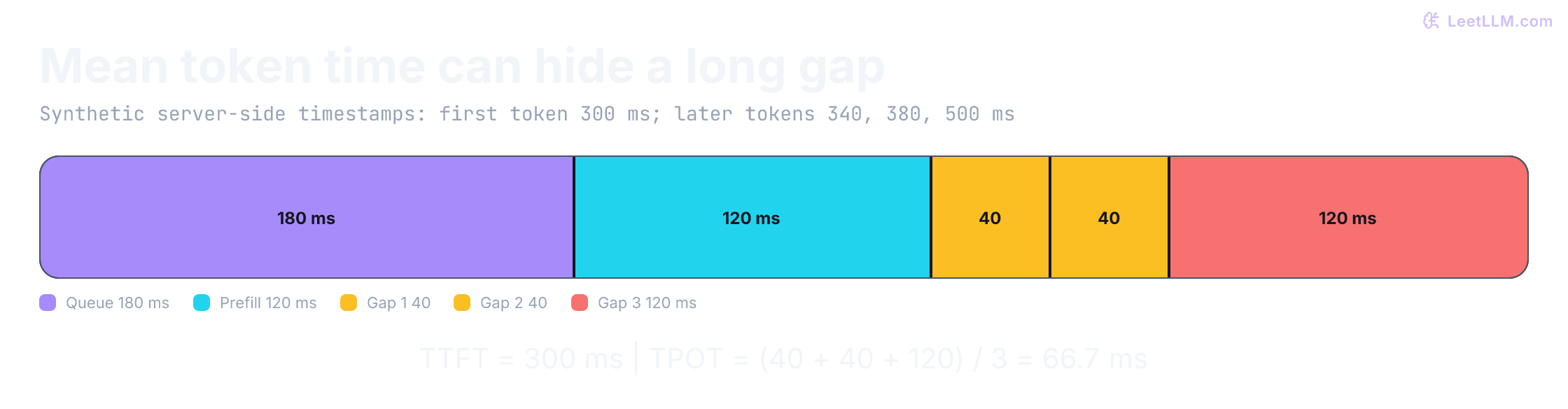
- Time Per Output Token (TPOT): The mean time per output token after the first token, total generation time after first token divided by (output tokens − 1), defined only when at least two output tokens arrive. TPOT is useful for capacity planning and average perceived speed. It isn't the same as every individual gap: a request can have healthy TPOT while a few ITL spikes still feel broken.
Measure server-side and client-side latency separately: network buffering can deliver several tokens in one chunk, and speculative decoding can emit several accepted tokens together. Neither chunk gaps nor output-event gaps reveal individual token timestamps automatically. Decode work is often memory-bandwidth bound for large decoder models at low batch size. Before setting an alert, record the measurement boundary, sampling unit, and aggregation weights.
For one synthetic stream, the first token arrives at 300 ms and later tokens at 340, 380, and 500 ms. TTFT is 300 ms; the gaps are 40, 40, and 120 ms. Mean TPOT is about 66.7 ms, hiding the 120 ms stall.
import math
import sys

def stream_metrics(arrival_ms, tokens_ms):
    if any(type(t) not in (int, float) or not -sys.float_info.max <= t <= sys.float_info.max
           or not math.isfinite(t) for t in [arrival_ms, *tokens_ms]):
        raise ValueError("timestamps must be finite")
    if not tokens_ms or tokens_ms[0] < arrival_ms:
        raise ValueError("missing first token or invalid arrival")
    gaps = [b - a for a, b in zip(tokens_ms, tokens_ms[1:])]
    if any(gap < 0 for gap in gaps):
        raise ValueError("token timestamps must be ordered")
    elapsed = tokens_ms[-1] - tokens_ms[0]
    ttft = tokens_ms[0] - arrival_ms
    if not all(math.isfinite(t) for t in [ttft, elapsed, *gaps]):
        raise ValueError("elapsed intervals must be finite")
    return ttft, gaps, elapsed / len(gaps) if gaps else None

ttft, gaps, tpot = stream_metrics(0, [300, 340, 380, 500])
assert (ttft, gaps) == (300, [40, 40, 120])
assert stream_metrics(0, [300])[2] is None
print(f"TTFT={ttft} ms; ITL={gaps} ms; TPOT={tpot:.1f} ms")
print("One-token completion: TPOT undefined, not zero.")
for timestamps in ([True], [10**400], [float("nan")], [-1e308, 1e308]):
    try:
        stream_metrics(-1e308, timestamps)
    except ValueError:
        pass
    else:
raise AssertionError("invalid stream clock accepted")TTFT=300 ms; ITL=[40, 40, 120] ms; TPOT=66.7 ms
One-token completion: TPOT undefined, not zero.The one-token result above is a mathematical definition. Current vLLM Prometheus metrics record TPOT as zero for requests with at most one output token; vllm bench serve excludes those requests from its TPOT statistics. Declare that eligibility rule when comparing dashboards with benchmarks.[1]
Now change the instrument, keeping the stream small. Suppose one output event delivers a token at 300 ms and the next delivers three tokens at 340 ms. How many latency observations do you actually have?
events = [(300, 1), (340, 3)]  # (event timestamp in ms, tokens delivered)
output_gaps = [b[0] - a[0] for a, b in zip(events, events[1:])]
tokens = sum(count for _, count in events)
request_tpot = (events[-1][0] - events[0][0]) / (tokens - 1)
assert output_gaps == [40] and tokens == 4
assert round(request_tpot, 1) == 13.3
print(f"output-event gaps: {output_gaps} ms; tokens delivered: {tokens}")
print(f"request TPOT: {request_tpot:.1f} ms; individual token gaps: unobserved")output-event gaps: [40] ms; tokens delivered: 4
request TPOT: 13.3 ms; individual token gaps: unobservedThe 40 ms event gap is useful evidence about a visible pause. Dividing by three gives average request pacing, but doesn't recover three individual token timestamps. Aggregation adds another distinction: a histogram with one observation per event weights long streams differently from a histogram with one observation per finished request.
Full-attention KV grows as the sequence grows. Fragmentation from clumsy allocation forces smaller batches and lower throughput.
A user says "first token is slow, but streaming is fast after that." Where do you trace first?
Answer
Trace the path before the first token: queue wait, worker readiness, cache misses, prefill, and first-token computation. The complaint alone can't identify prefill as the bottleneck. After the first token, watch stream gaps for jitter and request TPOT for mean decode speed.
Why GPU serving isn't web serving
The spike leaves two questions: what state does each request consume, and which signal says the fleet needs capacity? Four pieces answer them:
- The GPU is the scarce execution device. It's specialized, expensive, and you can't replace it with normal web servers.
- The model weights are the resident model state. Loading them takes time, and the worker can't decode until they are in GPU memory.
- The KV cache is per-request attention state. An active generation holds cache for its supplied context until completion or cancellation. An idle chat session doesn't necessarily retain a live request cache; optional prefix-cache blocks can persist as evictable entries. The cache pool fills up fast during a traffic spike.
- Autoscaling adds another ready worker. Bringing a new worker online takes time, and it can't help while the node, image, weights, and warmup are still loading.
Teams often scale because the GPU is busy. Use queue age and workload-aware demand to request capacity before deadlines expire. Check whether KV pressure or latency is caused by saturation, a bad node, or a dependency failure before scaling. A busy GPU can mean you're using the hardware well. A growing queue means users are waiting, and it needs an admission or capacity response.
That split between the execution device and the user-facing pressure signal is why the serving stack has two paths, not one web-style replica loop.
Why is "GPU utilization is high" not enough evidence to add replicas?
Answer
High GPU utilization can mean the current batch is healthy and full. Use demand and queue trends for capacity planning, then corroborate with active KV pressure and latency. An engine failure, skewed routing, or a slow dependency needs a different fix than more replicas.
The GPU serving stack
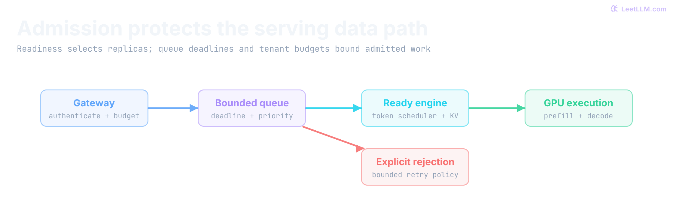
A request runs through the data path while a separate control loop adjusts future capacity. The hot path queues work, schedules batches, runs the model, and streams tokens. The control path watches that work, asks for more replicas, and waits for GPU nodes when those replicas can't land. Keep that split in mind as you map the stack:
-
Infrastructure layer: Kubernetes (EKS, GKE, or AKS) manages the GPU nodes. Unlike CPU nodes, GPU capacity is expensive and sometimes scarce, so a warm pool must be justified against latency targets and measured demand.
-
Control layer: In a KEDA-based setup, KEDA (Kubernetes Event-Driven Autoscaling) can activate a workload from zero and configure a Horizontal Pod Autoscaler (HPA) to scale running replicas from metrics. Karpenter (AWS) or Cluster Autoscaler can then provision GPU nodes when new pods can't be scheduled on existing capacity.[2][3]
-
Serving layer: The actual inference engines (vLLM, SGLang, TensorRT-LLM) that load models into GPU memory and handle token generation. At datacenter scale, a control plane such as NVIDIA Dynamo can orchestrate disaggregated prefill/decode pools across many of these engine replicas.[4]
-
Metrics: CPU and RAM metrics alone don't describe LLM-serving capacity. NVIDIA's DCGM (Data Center GPU Manager) exposes GPU-specific telemetry, while user-facing scaling signals usually come from the serving layer: queue depth, KV cache usage, TTFT, and inter-token latency.[1]
In this KEDA-based stack, which component decides pod count and which component adds GPU nodes?
Answer
KEDA and the generated HPA decide pod replica count from serving metrics. The Kubernetes scheduler tries to place those pods. Karpenter or Cluster Autoscaler adds GPU nodes only when pods can't be scheduled on existing capacity.
Scheduled, started, and ready are different states
A pod can be scheduled while its image is pulling, weights are loading, or warmup is failing. Kubernetes startup probes protect a slow initialization path from premature liveness restarts. Readiness controls whether a pod receives new Service traffic; liveness detects failures for which restarting the container is appropriate. Configure these endpoints for the actual serving process, not just a sidecar that returns 200.[5]
Don't turn every full batch into a liveness failure or every short queue into a readiness failure. Restarting or withdrawing all busy replicas makes overload worse. Keep bounded admission separate: reject excess work, preserve active streams, and scale from workload pressure. During drain, disable local admission immediately as well as failing readiness, because endpoint and load-balancer updates aren't instantaneous.
This CPU state machine tests those distinctions. It doesn't create Kubernetes probes or a concurrent HTTP server. A real server needs atomic admission accounting, cancellation cleanup, and a startup/health check that detects actual engine failure.
from dataclasses import dataclass, field

@dataclass
class Worker:
    loaded: bool = False
    warmed: bool = False
    engine_ok: bool = True
    draining: bool = False
    active: set[str] = field(default_factory=set)
    limit: int = 2

    def ready(self):
        return self.loaded and self.warmed and self.engine_ok and not self.draining

    def admit(self, request_id):
        if not self.ready():
            return 503
        if request_id in self.active:
            return 409
        if len(self.active) >= self.limit:
            return 429
        self.active.add(request_id)
        return 200

    def release(self, request_id):
        self.active.remove(request_id)

worker = Worker()
assert worker.admit("before-load") == 503
worker.loaded = True
assert worker.admit("before-warmup") == 503
worker.warmed = True
assert worker.admit("a") == worker.admit("b") == 200
assert worker.admit("a") == 409
assert worker.admit("c") == 429 and worker.ready() and worker.engine_ok
worker.draining = True
assert worker.admit("d") == 503 and worker.active == {"a", "b"}
worker.release("a")
worker.release("b")
assert not worker.active and not worker.ready()
worker.draining = False
worker.engine_ok = False
assert worker.admit("unhealthy") == 503
print("PASS load -> warmup -> admit; full worker rejects without restart")
print("PASS duplicate rejection, drain preserves active work, unhealthy worker rejects")PASS load -> warmup -> admit; full worker rejects without restart
PASS duplicate rejection, drain preserves active work, unhealthy worker rejectsServing frameworks
The stack named the engine. The next question is how that engine packs work so those GPU workers stay busy instead of waiting on the longest request.
Static batches wait for the longest reply
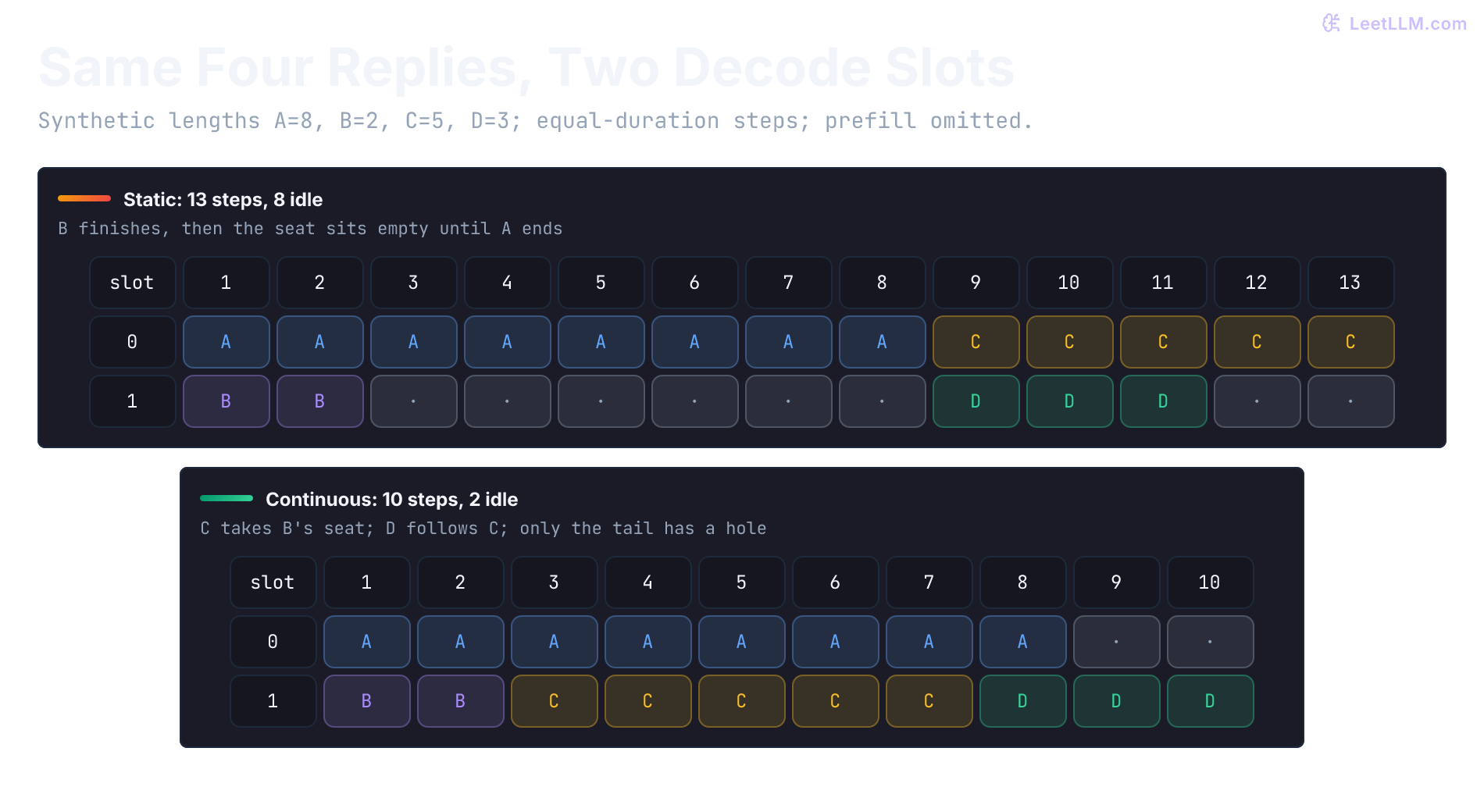
Early serving systems used static batching: waiting for requests to arrive, padding them to the same length, and processing them together. If one incident summary generates 100 tokens and another generates 1000, the GPU keeps the short request's empty slot until the long one finishes.
Modern frameworks use continuous batching (also known as iteration-level scheduling), pioneered by Orca[6]. The scheduler operates at the granularity of a single token generation step. As soon as a request finishes, queued work can join a later scheduling iteration if token, KV, and policy budgets permit.
What problem does continuous batching solve that static batching can't?
Answer
Static batching waits for the longest request in the batch, leaving completed slots idle. Continuous batching repacks work every token step, so finished requests free capacity immediately for queued requests.
The small simulation below uses generation lengths for four assistant replies. A static batch doesn't refill its two slots until both original replies finish; a continuous scheduler admits the next queued reply as soon as a slot opens.
from collections import deque

def run_batching(lengths: list[int], slots: int, continuous: bool) -> tuple[int, int]:
    if type(slots) is not int or slots <= 0:
        raise ValueError("slots must be a positive integer")
    if any(type(n) is not int or n <= 0 for n in lengths):
        raise ValueError("reply lengths must be positive integers")
    waiting = deque(lengths)
    active: list[int] = []
    token_steps = 0
    empty_slot_steps = 0

    while waiting or active:
        if not active or continuous:
            while waiting and len(active) < slots:
                active.append(waiting.popleft())

        token_steps += 1
        empty_slot_steps += slots - len(active)
        active = [remaining - 1 for remaining in active if remaining - 1 > 0]

    return token_steps, empty_slot_steps

reply_lengths = [8, 2, 5, 3]
for label, continuous in [("static", False), ("continuous", True)]:
    steps, empty = run_batching(reply_lengths, slots=2, continuous=continuous)
print(f"{label:10} token steps={steps:2} empty-slot steps={empty:2}")static token steps=13 empty-slot steps= 8
continuous token steps=10 empty-slot steps= 2With the same replies and slots, the continuous scheduler wastes fewer slot-iterations. Each step here has equal duration, all requests arrive at time zero, and prefill is omitted. The 13-to-10 result is an occupancy calculation, not a measured latency speedup; real step time changes with batch shape.
vLLM and PagedAttention
One widely used open-source serving engine is vLLM, which introduced PagedAttention[7]. The baseline systems studied in the PagedAttention paper pre-allocated a single contiguous block of GPU memory sized to the maximum sequence length a request might ever use. Because the actual length is revealed token-by-token during decoding, this approach created two problems:
- Internal fragmentation: most of the pre-allocated chunk sat empty for short requests.
- External fragmentation: free memory became scattered and couldn't satisfy new large contiguous allocations.
The PagedAttention paper found substantial reserved-memory waste in its evaluated baselines, including space reserved for future tokens as well as fragmentation. Those results describe those systems and workloads, not every earlier serving engine.[7] The result: the effective batch size stayed small, and throughput suffered even when the GPU had spare VRAM.
PagedAttention treats the KV cache like virtual memory in an operating system (OS). It breaks the KV cache into fixed-size blocks (pages) that can be stored in non-contiguous memory.
Logical vs. physical blocks
PagedAttention introduces two key abstractions:
- Logical KV blocks: The view of the KV cache from the model's perspective. It appears as a contiguous sequence of tokens.
- Physical KV blocks: The actual fixed-size chunks of memory allocated in HBM (High Bandwidth Memory, the GPU's ultra-fast RAM) to store these tokens.
A Block Table maintains the mapping between logical and physical blocks. When a new token is generated, vLLM checks if the current physical block has space. If not, it allocates a new physical block from a pre-allocated pool and updates the mapping. The PagedAttention paper reports much tighter memory use and higher throughput because batches can pack around real sequence lengths instead of worst-case reservations.[7]
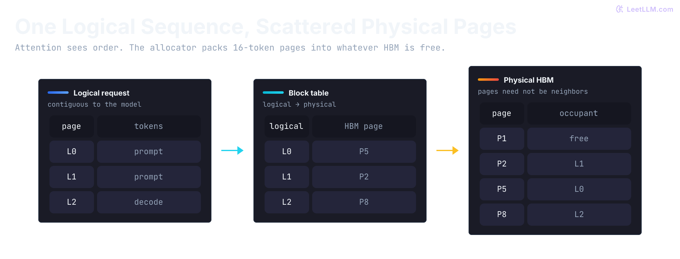
PagedAttention gives the runtime fine-grained control over KV blocks. In current vLLM deployments, request-to-request reuse of a shared prompt prefix usually comes from automatic prefix caching, which reuses previously computed KV blocks when a new request shares the same prefix.[8]
How are PagedAttention and prefix caching different?
Answer
PagedAttention is memory allocation: it stores each request's KV cache in fixed-size physical blocks to reduce fragmentation. Prefix caching is reuse: it avoids recomputing KV blocks when a new request shares an already-computed prefix.
The allocation arithmetic for four conversations makes the waste visible. The fixed reservation policy reserves each request for its maximum allowed length, while paging reserves blocks only for tokens currently stored:
import math

cached_tokens = [320, 75, 900, 250]
max_tokens_per_request = 2048
tokens_per_block = 16

fixed_blocks = len(cached_tokens) * math.ceil(max_tokens_per_request / tokens_per_block)
paged_blocks = sum(math.ceil(tokens / tokens_per_block) for tokens in cached_tokens)
used_tokens = sum(cached_tokens)

print(f"tokens currently cached: {used_tokens}")
print(f"fixed reservation blocks: {fixed_blocks}")
print(f"paged allocation blocks:   {paged_blocks}")
print(f"reserved tokens avoided: {(fixed_blocks - paged_blocks) * tokens_per_block}")tokens currently cached: 1545
fixed reservation blocks: 512
paged allocation blocks: 98
reserved tokens avoided: 6624Paging doesn't make attention state free. The 98 allocated blocks provide 1,568 token slots for 1,545 stored tokens, leaving 23 unused slots in final blocks. The comparison omits shared prefixes, speculative lookahead, and implementation metadata.
The overall request lifecycle coordinates these components. Client requests enter an API server queue, are packed by a continuous batching scheduler, and finally executed by a model engine using PagedAttention and, when enabled, prefix caching on the GPU cluster:
Compare engines against one request shape
Popularity doesn't tell you whether an engine fits the incident assistant. Hold request shape, SLOs, hardware, precision, and correctness checks fixed, then compare the execution paths:
| Engine | Mechanism to evaluate | Boundary to verify |
|---|---|---|
| vLLM | Continuous batching, paged KV, prefix reuse | Model/backend support and the same workload's goodput |
| TensorRT-LLM[9] | NVIDIA-optimized inference; the current migration guide makes PyTorch the sole execution backend | Pin the release: legacy engine-build instructions no longer apply to the current API |
| TGI[10] | Existing launcher, streaming, metrics, and batching | Maintenance mode; evaluate migration cost for existing deployments |
| SGLang[11] | Radix-tree prefix reuse and scheduling | Cache-hit mix, model support, and per-target measurements |
| llama.cpp[12] | GGUF and multiple hardware backends | Backend support, model layout, and target-machine latency |
The TGI documentation describes TGI as maintenance mode and directs users toward newer optimized engines such as vLLM and SGLang for new deployments.[10] These engines are the data plane that loads weights and generates tokens. At datacenter scale, a separate control plane such as NVIDIA Dynamo can sit above them to provide disaggregated prefill/decode scheduling and KV-aware routing across engine replicas (covered later under disaggregation).[4]
This unexecuted GPU configuration illustrates vLLM for the 8B incident assistant. /models/dev-assistant-8b is a placeholder for your approved local checkpoint, not a downloadable model. The configuration loads one GPU's worth of weights, sets a high memory-utilization budget for weights, KV blocks, and runtime buffers, and turns on chunked prefill so long prompts can share scheduling budget with decode traffic.[13] Inputs are the model identifier and hardware constraints. The prompt includes synthetic incident evidence so the model isn't asked to invent a rollback plan from an incident ID alone. Use the checkpoint's chat template for an instruction-tuned model.
Before choosing a serving framework, what workload facts should you map?
Answer
Map latency SLO, expected concurrency, prompt length distribution, shared-prefix rate, GPU hardware, quantization tolerance, and operational ownership. No engine choice follows from an SLO label alone; benchmark eligible engines against the same trace.
from vllm import LLM, SamplingParams

# Illustrative settings, not a tested deployment or universal defaults.
llm = LLM(
    model="/models/dev-assistant-8b",
    tensor_parallel_size=1,
    gpu_memory_utilization=0.90,      # Weights, KV blocks, and runtime buffers
    max_model_len=8192,
    enable_chunked_prefill=True,      # Keep the knob explicit in reviewed configs
    enable_prefix_caching=True,       # Reuse KV blocks when requests share a prefix
    max_num_batched_tokens=16384,     # Main TTFT/TPOT trade-off knob for chunked prefill
)

params = SamplingParams(
    temperature=0.7,
    top_p=0.95,
    max_tokens=512
)

prompt = "Synthetic incident INC-1842: rollout v7 raises errors; rollback target is v6. Summarize these facts only."
outputs = llm.chat([{"role": "user", "content": prompt}], params)
print(outputs[0].outputs[0].text)
All of these knobs are workload-dependent. Tune them against TTFT and TPOT SLOs, rather than raw tokens/sec alone.
That SLO-first capacity measure is goodput: the highest offered request rate at which a predeclared fraction of requests stays within both a TTFT objective and a decode objective. DistServe uses mean TPOT for its decode constraint; if your product promises a tail ITL bound, declare that gate separately instead of silently treating TPOT as ITL.[14] Use goodput when you size fleets, set autoscaling success criteria, and decide whether prefill-decode disaggregation is worth its transfer cost.
Benchmark the path you'll operate
A memory formula and a goodput target narrow the search, but neither tells you what one replica can serve. Measure the request path that users will hit. A list of identical 512-token prompts answers a toy throughput question; it won't expose queue growth, long-prefill interference, prefix-cache misses, or the cost of streaming tails.
Start with a versioned trace. Each row should carry an arrival time, prompt-token count, output-token cap, shared-prefix ID, tenant or priority class, and streaming flag. For the incident assistant, this small fixture makes the workload concrete without pretending to be a production result:
| Request class | Prompt tokens | Output tokens | Arrival pattern | Pressure it exposes |
|---|---|---|---|---|
| Interactive incident summary (60%) | 256 to 512 | 64 to 192 | Bursty freeze traffic | TTFT and tail ITL |
| Long-context incident review (25%) | 4,000 to 8,000 | 128 to 512 | Mixed with interactive work | Prefill contention and KV growth |
| Batch diff or policy review (15%) | 2,000 to 4,000 | 512 to 1,024 | Lower-priority background load | Decode occupancy and backpressure |
Warm the model, tokenizer, caches, and scheduler before recording steady-state runs. Sweep concurrency to expose queueing, then use a bounded request-rate sweep to find the saturation point. Keep the trace, arrival process, warmup rule, and stop condition fixed across candidates. If an offered rate outruns completion, an unbounded client queue can make every later latency number meaningless.
Record five parts with every result: the GPU model and count, interconnect and topology; engine, driver, CUDA, and model versions; precision, quantization, batching, and parallelism settings; the exact baseline configuration; and a correctness check. The baseline must receive the same trace, warmup, concurrency, and tuning effort. Correctness can combine deterministic token or logit checks where available with a golden request set that verifies citations, tool calls, refusal behavior, and output schema. A faster run that changes the answer contract isn't an improvement.
Report the full curve, not its best point: p50/p95/p99 TTFT, p95/p99 ITL, request-mean TPOT, completed requests per second, error and rejection rates, KV utilization, and cost per successful request. At each offered rate, show the fraction meeting the declared TTFT and decode SLOs. The highest sustainable rate that reaches the required attainment is the goodput point. This evidence tells you whether a new GPU, quantization setting, batch limit, or disaggregated data plane fixed the bottleneck.
GPU infrastructure
Sizing and selection
Turn that request shape into a hardware budget. Selecting the right GPU depends on model size, quantization, and expected traffic. The dominant factors are GPU memory capacity (often called VRAM; datacenter accelerators such as H100 use HBM) to fit weights plus KV cache, and memory bandwidth to serve tokens quickly.
To estimate memory requirements for capacity, use this formula:
Where:
- (e.g., Qwen3.6-27B's language component at BF16 is about bytes = 54 GB). Its vision encoder and any additional loaded prediction modules need separate accounting.[15]
- (the factor of 2 accounts for both the key and value tensors)
- covers fixed-size recurrent or linear-attention state per active request. It doesn't grow with sequence length, but it still consumes memory and must be added separately.
Two distinctions matter. The older shorthand using Hidden Dim assumes full multi-head attention. Many modern decoder models use grouped-query attention (GQA) or multi-query attention (MQA), so the number of KV heads is much smaller than the total attention head count. Hybrid models also mix full attention with linear or recurrent layers. Only full-attention layers append growing K/V tensors; linear layers keep a different state shape.
The function below estimates a memory-fit lower bound from model size and cache expectations. It takes the model size plus the architecture terms that control KV growth (num_kv_layers, num_kv_heads, head_dim, context length, and concurrency), then reports an optimistic aggregate-memory lower bound for several GPU types. The per-GPU budgets below are illustrative decimal GB allowances, not measured free memory. Interconnect topology, kernel support, and measured latency still decide whether a configuration is deployable:
from collections.abc import Mapping
import math
import sys

def estimate_gpu_requirements(
    model_params_b: float,      # Billions of parameters
    num_kv_layers: int,
    num_kv_heads: int,
    head_dim: int,
    context_len: int,
    target_concurrency: int,
    weight_bytes: int = 2,      # BF16/FP16=2, INT8=1, FP8=1
    kv_bytes: int = 2,          # KV cache often stays in BF16/FP16
    hybrid_state_bytes_per_request: int = 0,
    overhead_factor: float = 1.15,
) -> Mapping[str, object]:
    numeric = (model_params_b, weight_bytes, kv_bytes, overhead_factor)
    if any(type(v) not in (int, float) or not 0 < v <= sys.float_info.max
           or not math.isfinite(v) for v in numeric) or overhead_factor < 1:
        raise ValueError("finite positive sizes and overhead >= 1 are required")
    counts = (num_kv_layers, num_kv_heads, head_dim, context_len, target_concurrency,
              hybrid_state_bytes_per_request)
    if any(type(v) is not int or v < 0 for v in counts):
        raise ValueError("architecture and workload counts must be nonnegative integers")
    if num_kv_layers and (num_kv_heads == 0 or head_dim == 0):
        raise ValueError("growing KV layers require positive head count and dimension")
    # 1. Model weights. model_params_b is already in billions, so
    # model_params_b * bytes gives an approximate size in decimal GB.
    weight_memory_gb = model_params_b * weight_bytes

    # 2. Sequence-growing KV. Count only layers that append standard K/V.
    kv_memory_bytes = (
        2
        * num_kv_layers
        * num_kv_heads
        * head_dim
        * context_len
        * target_concurrency
        * kv_bytes
    )
    kv_memory_gb = kv_memory_bytes / 1e9

    # 3. Fixed-size recurrent/linear-attention state grows with active
    # requests, not with prompt length. Runtime buffers still need profiling.
    hybrid_state_gb = (
        hybrid_state_bytes_per_request * target_concurrency / 1e9
    )

    total_gb = (
        weight_memory_gb + kv_memory_gb + hybrid_state_gb
    ) * overhead_factor

    gpu_options: dict[str, Mapping[str, int]] = {
        "L4_24GB": {"mem": 24, "needed": max(1, int(math.ceil(total_gb / 22)))},
        "A100_40GB": {"mem": 40, "needed": max(1, int(math.ceil(total_gb / 38)))},
        "A100_80GB": {"mem": 80, "needed": max(1, int(math.ceil(total_gb / 76)))},
        "H100_80GB": {"mem": 80, "needed": max(1, int(math.ceil(total_gb / 76)))},
        "H200_141GB": {"mem": 141, "needed": max(1, int(math.ceil(total_gb / 134)))},
    }
    return {
        "weights_gb": weight_memory_gb,
        "kv_cache_gb": kv_memory_gb,
        "hybrid_state_gb": hybrid_state_gb,
        "total_with_overhead_gb": total_gb,
        "gpu_options": gpu_options,
    }

def show_case(name: str, result: Mapping[str, object]) -> None:
    gpu_options = result["gpu_options"]
    print(name)
    print(f"  weights: {result['weights_gb']:.1f} GB")
    print(f"  growing KV: {result['kv_cache_gb']:.1f} GB")
    print(f"  hybrid state: {result['hybrid_state_gb']:.1f} GB")
    print(f"  total with overhead: {result['total_with_overhead_gb']:.1f} GB")
    print(f"  H100_80GB needed: {gpu_options['H100_80GB']['needed']}")

chat_8b = estimate_gpu_requirements(
    model_params_b=8,
    num_kv_layers=32,
    num_kv_heads=8,
    head_dim=128,
    context_len=4096,
    target_concurrency=8,
)

# Qwen3.6-27B has 16 full-attention layers and 48 linear-attention
# layers. Budget each linear layer's FP32 recurrent matrix from the
# published head layout; deployed runtimes may add convolution state.
linear_layers = 48
linear_key_heads = 16
linear_key_dim = 128
linear_value_heads = 48
linear_value_dim = 128
fp32_bytes = 4
qwen_linear_state_bytes_per_request = (
    linear_layers
    * linear_key_heads
    * linear_key_dim
    * (linear_value_heads // linear_key_heads)
    * linear_value_dim
    * fp32_bytes
)

qwen36_27b = estimate_gpu_requirements(
    model_params_b=27,
    num_kv_layers=16,
    num_kv_heads=4,
    head_dim=256,
    context_len=8192,
    target_concurrency=4,
    hybrid_state_bytes_per_request=qwen_linear_state_bytes_per_request,
)

show_case("8B BF16, 4k context, 8 active requests", chat_8b)
show_case("Qwen3.6-27B language-only budget, BF16, 8k context, 4 active requests", qwen36_27b)8B BF16, 4k context, 8 active requests
weights: 16.0 GB
growing KV: 4.3 GB
hybrid state: 0.0 GB
total with overhead: 23.3 GB
H100_80GB needed: 1
Qwen3.6-27B language-only budget, BF16, 8k context, 4 active requests
weights: 54.0 GB
growing KV: 2.1 GB
hybrid state: 0.6 GB
total with overhead: 65.3 GB
H100_80GB needed: 1Qwen3.6-27B has 64 total language layers, arranged as 16 groups of three linear-attention layers followed by one full-attention layer.[15] Only those 16 full-attention layers contribute sequence-growing KV in this formula. The example separately adds about 0.15 GB of fixed recurrent matrix state per active request as a teaching lower bound. It budgets the language component only; the official model card documents a language-only serving mode that skips the vision encoder. Account separately for any loaded vision/prediction modules, convolution state, allocator metadata, and temporary buffers. This low-concurrency 8k budget is below the assumed 76 GB H100 allowance. It doesn't prove per-rank fit: sharding, replicated tensors, GQA KV replication, and runtime layout can prevent an aggregate-memory total from fitting.
Why does the growing-KV formula use num_kv_heads and only full-attention layers?
Answer
GQA and MQA share key/value heads across multiple query heads, so KV cache stores K/V for the smaller head count. In a hybrid model, only full-attention layers append those tensors at every token. Linear-attention layers keep separate fixed-size recurrent state, which belongs in another budget term.
Keep four budgets separate: checkpoint residency, active weight bytes read per token, attention or recurrent state, and communication. A mixture-of-experts (MoE) model keeps its resident expert pool in memory even though each token uses only selected experts. “3B active” therefore isn't a 6 GB BF16 residency estimate. Offloaded experts change that tradeoff by adding transfers.
A quantized file's download size isn't necessarily its runtime weight footprint. Runtime packing, quantization scales, temporary dequantization, and tensors left at higher precision all matter. Use runtime measurements before turning artifact size into a capacity or bandwidth claim.
Multi-Instance GPU (MIG)
For cost-efficient autoscaling of smaller models, Multi-Instance GPU (MIG) can partition a single GPU into hardware-isolated slices. Ampere- and Hopper-class parts such as A100, H100, and H200 can expose up to seven instances on supported SKUs.[16] Instead of dedicating an entire large GPU to a single 7B model, you can run multiple replicas on isolated slices with dedicated compute and memory resources.
Find the decode ceiling
For low-batch decode of large decoder models, weight reads commonly make the system memory-bandwidth bound. Batching, cache traffic, kernels, and multi-GPU communication can change which limit dominates.
A weight-only throughput ceiling (), assuming one complete read of the active weight footprint from HBM per token at batch size one, is (a simplified model derived from memory-bandwidth analyses such as Pope et al.)[17]:
Reading the formula
In this simplified batch-size-one model, the GPU streams the relevant active weight footprint from HBM for each generated token. Little weight reuse happens across sequential steps (the KV cache reuses activations, not the static weights). For a dense model, the active footprint is approximately the full model. For an MoE model, use shared weights plus routed expert bytes measured for the token; full checkpoint residency isn't the decode denominator.
This is the reciprocal of the time required to load the relevant weight footprint from HBM once. Using the H100 SXM specification of 3.35 TB/s and a hypothetical dense runtime that reads 54 GB of weights per token gives a weight-only ceiling of roughly 62 tokens/sec for one sequence.[18] This assumes the entire 54 GB is active weight traffic; checkpoint size alone can't establish that denominator. Real systems achieve lower throughput because:
- KV cache reads/writes, activations, and sampling also consume memory bandwidth
- Kernel launch, attention computation, and scheduler overhead
- The achieved bandwidth of fused kernels is rarely 100 % of the theoretical peak
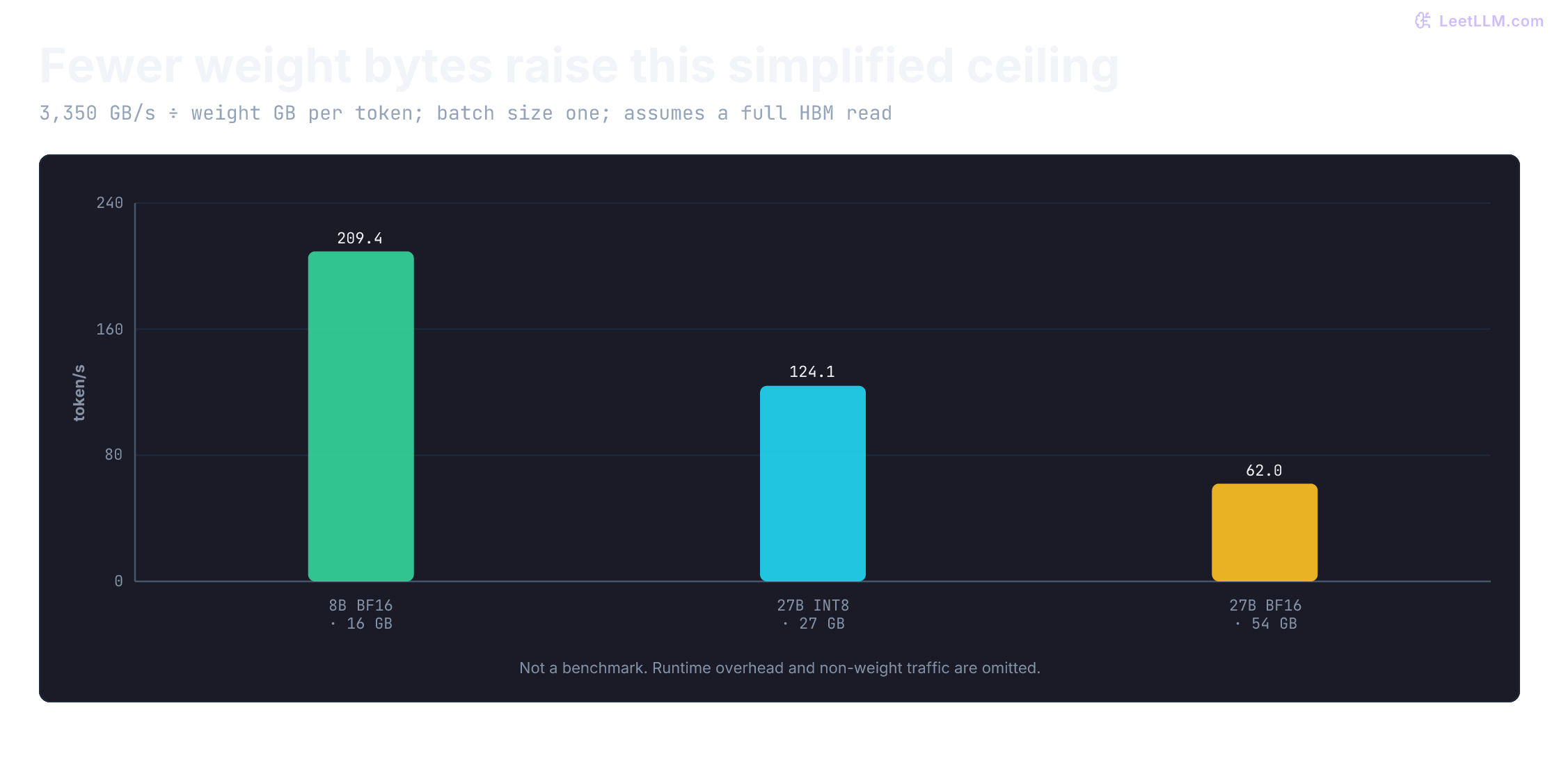
This bound explains why quantization can improve decode throughput: halving only the weight-footprint term (FP16 to INT8, for example) doubles this simplified ceiling. Actual speedup is smaller or different when kernel support, KV-cache traffic, compute, or communication dominate. It also shows why large models may require tensor parallelism: the denominator grows while per-GPU bandwidth stays fixed.
The next calculation is deliberately a ceiling, not a benchmark. It isolates weight traffic so you can see what quantization changes before adding runtime overhead:
bandwidth_gb_s = 3350
weight_footprints_gb = {
    "8B BF16": 16,
    "Dense 27B INT8": 27,
    "Dense 27B BF16": 54,
}

for name, weights_gb in weight_footprints_gb.items():
    ceiling_tps = bandwidth_gb_s / weights_gb
    print(f"{name:16} weight-only ceiling = {ceiling_tps:6.1f} token/s")

print("MoE ceiling: measure shared + routed expert bytes/token, not full checkpoint bytes")8B BF16 weight-only ceiling = 209.4 token/s
Dense 27B INT8 weight-only ceiling = 124.1 token/s
Dense 27B BF16 weight-only ceiling = 62.0 token/s
MoE ceiling: measure shared + routed expert bytes/token, not full checkpoint bytesWhy does weight quantization often improve decode speed besides memory footprint?
Answer
Decode repeatedly streams model weights from HBM. Smaller weights reduce bytes loaded per token, raising the memory-bandwidth upper bound for tokens per second.
Tensor parallelism
For models that don't fit comfortably on a single GPU, or that fit weights but not the target KV-cache and headroom budget, we use Tensor Parallelism (TP). TP splits individual weight matrices (e.g., ) across multiple GPUs so each device computes one shard. This technique was pioneered in the Megatron-LM training system[19] and adapted for inference serving.
TP operates by slicing matrix computations, so participating GPUs exchange partial results through collective communication within each transformer layer. In the standard Megatron-style transformer block, budget two collectives per layer: one around the attention output projection and one around the feed-forward output projection. Exact collective type and placement depend on row/column partitioning and runtime, but counting only one synchronization per layer understates communication.
- Intra-node: TP works best when GPUs share a very fast fabric such as NVLink (NVIDIA high-bandwidth interconnect) or NVSwitch (NVIDIA multi-GPU switch).
- Inter-node: TP can extend across RDMA (Remote Direct Memory Access) or InfiniBand, but the communication tax rises quickly. For multi-node serving, teams often keep TP within a node when they can, and use Pipeline Parallelism (PP) or independent replicas across nodes instead. PP only communicates activations at stage boundaries, but it introduces pipeline bubbles and can worsen tail latency.
When should you prefer tensor parallelism within a node over spreading one model across nodes?
Answer
Prefer intra-node tensor parallelism when the GPUs share fast NVLink or NVSwitch and the model needs matrix shards on every layer. Crossing nodes adds communication latency; use pipeline parallelism or independent replicas when inter-node fabric would dominate tail latency.
This diagram shows where bytes move in each split:
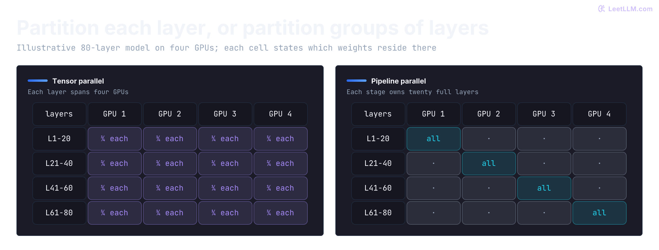
Communication frequency isn't total cost: tensor-parallel messages may travel over faster links, while pipeline stages can create bubbles. This toy count makes the first screening question explicit:
layers = 80
pipeline_stages = 4
decode_steps = 32
tp_collectives_per_layer = 2

tp_sync_events = layers * tp_collectives_per_layer * decode_steps
pp_boundary_events = (pipeline_stages - 1) * decode_steps

print(f"tensor-parallel sync events: {tp_sync_events}")
print(f"pipeline boundary transfers: {pp_boundary_events}")
print("Measure bytes, fabric speed, and pipeline bubbles before choosing.")tensor-parallel sync events: 5120
pipeline boundary transfers: 96
Measure bytes, fabric speed, and pipeline bubbles before choosing.Autoscaling strategies
Once the engine is measured, autoscaling must answer two different questions: are requests waiting for a ready worker, and is there enough GPU hardware to place another worker? CPU-based autoscaling alone misses the first question because CPU isn't usually the scarce inference resource. CPU can still reveal overloaded gateways or tokenizers. GPU utilization can also be misleading: a GPU might be busy with a healthy batch, or it might be memory-bound while compute duty cycle looks modest.
Key metrics
Useful autoscaling evidence comes from two sources: NVIDIA's DCGM (Data Center GPU Manager) for hardware-level visibility, and the serving framework itself for application-level signals. In current vLLM, the Prometheus endpoint exposes vllm:num_requests_waiting, vllm:num_requests_running, vllm:kv_cache_usage_perc, and vllm:time_to_first_token_seconds. Use vllm:inter_token_latency_seconds for inter-output-event gaps and vllm:request_time_per_output_token_seconds for per-request TPOT. They aren't interchangeable when outputs bundle tokens or aggregation weights differ. The request histogram also includes zero-valued TPOT observations for completions with at most one token.[1]
| Metric | Source | Why It Matters | Example Signal |
|---|---|---|---|
| Request Queue Depth | Serving framework or gateway | Backlog of waiting requests | Sustained upward trend |
| KV Cache Utilization | Serving framework | Memory pressure; active-block pressure can constrain admission | Sustained high watermark |
| GPU Duty Cycle | DCGM | Useful supporting telemetry, but easy to misread alone | Corroborate with app metrics |
| Time To First Token (TTFT) | Serving framework | User-facing first-token latency | SLO breach |
| Stream gap (ITL / TBT) | Declared token/event instrument | Jitter after first output; vLLM samples output events | Tail (p95/p99) SLO breach in the declared unit |
| Time Per Output Token (TPOT) | Per-request serving metric | Mean request pacing after first token, elapsed time / (n_out − 1) for eligible requests | Request-level decode SLO breach |
DCGM (Data Center GPU Manager) exposes hardware-level GPU metrics like temperature, power, clock rates, engine activity, and memory traffic. While GPU utilization seems like an obvious scaling signal, it isn't a complete serving-capacity signal. High activity can reflect useful work or a bottleneck elsewhere in the memory path; low activity can reflect sparse or bursty work. Neither tells you how long requests are waiting or how many KV blocks remain schedulable.
That's why application-level metrics (queue depth, KV cache utilization, TTFT, ITL, TPOT) are more reliable scaling signals. They expose user pressure more directly, but still need interpretation. Cached blocks with no active references may be evictable; distinguish active allocation pressure from reusable cache contents. In vLLM, kv_cache_usage_perc is a fraction: 0.85 means 85%, not 0.85%.[8] Alert on both mean TPOT and the ITL histogram: a healthy request-mean can hide a few long gaps that still break streaming. Capacity success is goodput under those dual latency objectives, not GPU busy percent. The exact thresholds are workload-specific, so treat any numbers you see in dashboards or sample code as starting points, not universal defaults.
Which metric should page you first: average GPU utilization or sustained request queue depth?
Answer
Sustained request queue depth. It means users are waiting before admission. GPU utilization is supporting context, but it doesn't tell you whether the service has enough schedulable KV capacity for current demand.
KEDA and Karpenter integration
One control-loop design works as follows: the serving framework exposes metrics via Prometheus. KEDA can activate a scaled workload from zero and configure the generated HPA for running replica scaling. If the scheduler can't place new GPU pods, the node autoscaler layer (often Karpenter or Cluster Autoscaler) provisions nodes that satisfy pod requirements.[2][3]
This two-layer approach separates desired pod count from hardware supply. Ready pods may scale quickly if spare GPU capacity exists; new nodes and model loading can take far longer. The useful warm buffer is a measured tradeoff between idle GPU cost and the latency damage of a cold burst.
Why is GPU autoscaling a two-loop problem?
Answer
Replica count changes quickly, but GPU node capacity appears slowly. Pod scaling decides desired serving capacity; node autoscaling supplies hardware only after unschedulable GPU pods reveal the cluster lacks the right nodes.
The autoscaling loop should separate replica pressure from hardware supply:
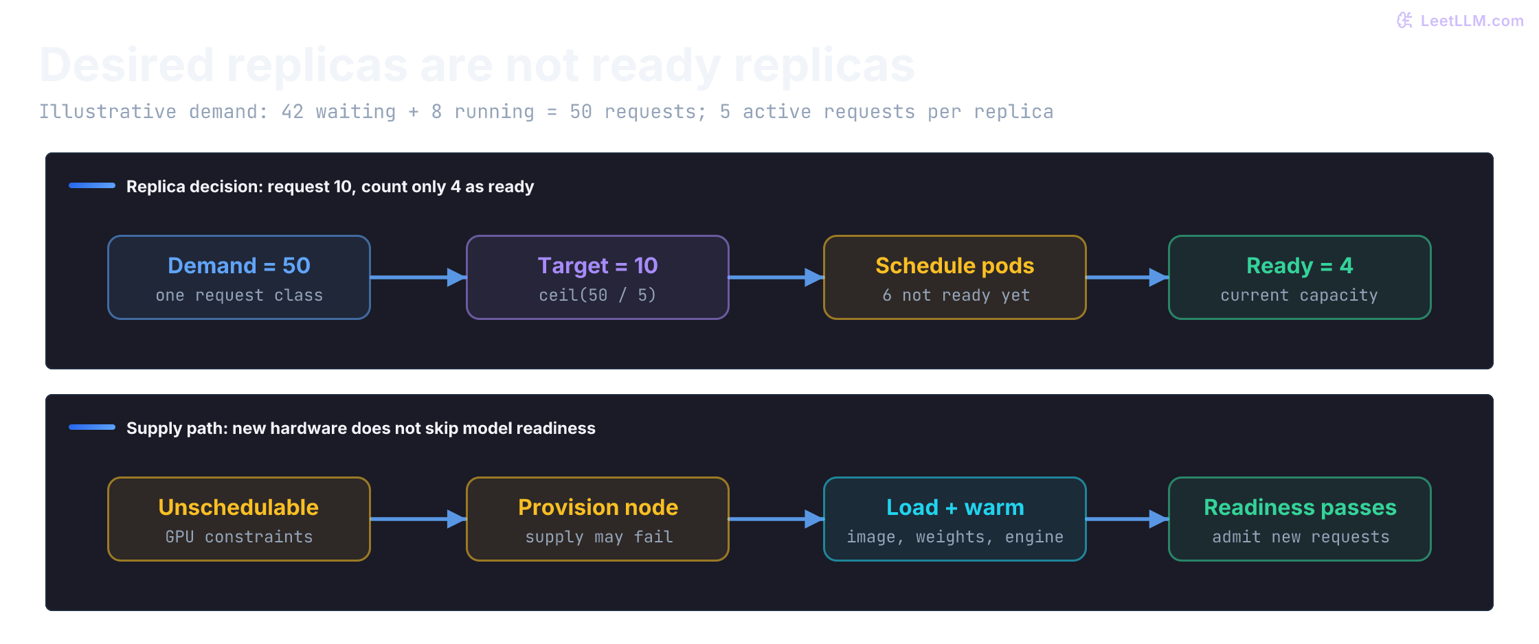
KEDA 2.20 activates workloads and exposes metrics to HPA; it doesn't supply an HTTP request buffer automatically. Scaling from zero needs an always-available gateway, durable queue, or another external event source. Scraping only the nonexistent serving pods can't reveal new demand.[2]
HPA's downscale stabilization is separate from scale-up. In KEDA 2.20, cooldownPeriod concerns returning to zero; it isn't a blanket pause after every scale event. A 300-second cooldown applied to both directions can strand a burst behind five minutes of avoidable delay. Configure downscale stabilization in HPA's behavior, and check the ScaledObject specification for the installed KEDA release.[20][21]
This CPU controller is an explicit teaching policy, not a reimplementation of HPA. It uses one homogeneous request class and a five-active-request capacity assumption. It counts desired replicas, not only ready ones, so pending capacity isn't requested again on every poll. Stale or missing telemetry holds capacity and raises an observable reason; low demand must persist for 300 seconds before one replica is removed.
from dataclasses import dataclass
import math
import sys

def finite_time(value):
    return (type(value) in (int, float)
            and -sys.float_info.max <= value <= sys.float_info.max
            and math.isfinite(value))

@dataclass(frozen=True)
class Demand:
    sampled_at: float
    waiting: int
    running: int

class GPUAutoscaler:
    def __init__(self, minimum=1, maximum=20, per_replica=5, down_window_s=300):
        if (any(type(n) is not int for n in (minimum, maximum, per_replica))
                or not finite_time(down_window_s)
                or not (1 <= minimum <= maximum and per_replica > 0 and down_window_s >= 0)):
            raise ValueError("invalid scaling bounds")
        self.minimum, self.maximum = minimum, maximum
        self.per_replica, self.down_window_s = per_replica, down_window_s
        self.low_since = None
        self.last_now = None

    def recommend(self, demand, desired, ready, now):
        if not finite_time(now) or (self.last_now is not None and now < self.last_now):
            raise ValueError("time must be finite and monotonic")
        if (any(type(n) is not int for n in (desired, ready))
                or not (self.minimum <= desired <= self.maximum and 0 <= ready <= desired)):
            raise ValueError("invalid replica state")
        self.last_now = now
        if demand is None or not finite_time(demand.sampled_at) or not 0 <= now - demand.sampled_at <= 30:
            self.low_since = None
            return desired, "telemetry unavailable: hold and alert"
        if any(type(n) is not int or n < 0 for n in (demand.waiting, demand.running)):
            raise ValueError("request counts must be nonnegative integers")
        requests = demand.waiting + demand.running
        needed = max(self.minimum, (requests + self.per_replica - 1) // self.per_replica)
        target = min(self.maximum, needed)
        if target > desired:
            self.low_since = None
            reason = "scale up; enforce admission budget" if needed > self.maximum else "scale up"
            return target, reason
        if needed > self.maximum:
            self.low_since = None
            return desired, "at limit: enforce admission budget"
        if target == desired or ready < desired:
            self.low_since = None
            return desired, "hold; desired capacity already requested"
        if self.low_since is None:
            self.low_since = now
        if now - self.low_since >= self.down_window_s:
            self.low_since = now
            return max(target, desired - 1), "drain one replica before removal"
        return desired, "downscale stabilization"

scaler = GPUAutoscaler()
assert scaler.recommend(Demand(0, 42, 8), 4, 4, 0)[0] == 10
assert scaler.recommend(Demand(1, 42, 8), 10, 4, 1)[0] == 10
assert scaler.recommend(Demand(2, 48, 8), 10, 4, 2)[0] == 12
assert scaler.recommend(None, 12, 12, 3)[0] == 12
assert scaler.recommend(Demand(0, 0, 0), 12, 12, 40)[0] == 12
for now, expected in ((100, 12), (399, 12), (400, 11)):
    assert scaler.recommend(Demand(now, 0, 1), 12, 12, now)[0] == expected
assert scaler.recommend(Demand(401, 200, 0), 20, 20, 401)[1].startswith("at limit")
assert scaler.recommend(Demand(402, 200, 0), 4, 4, 402) == (20, "scale up; enforce admission budget")
for timestamp in (True, float("nan"), 10**400):
    assert scaler.recommend(Demand(timestamp, 0, 0), 20, 20, 403)[1].startswith("telemetry unavailable")
try:
    scaler.recommend(Demand(403, -1, 0), 20, 20, 403)
except ValueError:
    pass
else:
    raise AssertionError("negative demand accepted")
print("PASS immediate scale-up, pending-capacity deduplication, telemetry hold")
print("PASS 300s downscale boundary, replica cap, invalid demand")PASS immediate scale-up, pending-capacity deduplication, telemetry hold
PASS 300s downscale boundary, replica cap, invalid demandThe autoscaler requests capacity; it doesn't create it instantly. The next event simulation follows 100 requests arriving together. Each occupies one slot for ten seconds; each replica has five slots. New replicas become ready at 207 seconds, and requests may wait at most 30 seconds before admission. These durations are synthetic. Prefill and token-level scheduling are omitted, so this tests queue deadlines, not LLM goodput.
import heapq
import sys

def burst(warm_replicas, *, requests=100, slots=5, service_s=10, cold_ready_s=207, max_wait_s=30):
    if (any(type(n) is not int for n in (warm_replicas, requests, slots))
            or any(type(t) not in (int, float) or not 0 <= t <= sys.float_info.max
                   for t in (service_s, cold_ready_s, max_wait_s))
            or not (0 <= warm_replicas <= 20 and requests >= 0 and slots > 0 and service_s > 0
            and cold_ready_s >= 0 and max_wait_s >= 0)):
        raise ValueError("invalid burst inputs")
    # Each heap item is one slot's next availability and whether it is cold.
    workers = [(0, False)] * (warm_replicas * slots)
    workers += [(cold_ready_s, True)] * ((20 - warm_replicas) * slots)
    heapq.heapify(workers)
    admitted = rejected = cold_admissions = 0
    for _ in range(requests):
        start, cold = heapq.heappop(workers)
        if start > max_wait_s:
            rejected += 1
            heapq.heappush(workers, (start, cold))
            continue
        admitted += 1
        cold_admissions += int(cold)
        heapq.heappush(workers, (start + service_s, cold))
    return admitted, rejected, cold_admissions

for warm, expected in ((0, (0, 100, 0)), (1, (20, 80, 0)), (3, (60, 40, 0)), (20, (100, 0, 0))):
    result = burst(warm)
    assert result == expected
    print(f"warm={warm:2}: admitted={result[0]:3}, expired={result[1]:3}, cold admissions={result[2]}")
assert burst(1, max_wait_s=300) == (100, 0, 0)
print("With a 300s queue budget, one warm replica handles the burst before cold replicas arrive.")warm= 0: admitted= 0, expired=100, cold admissions=0
warm= 1: admitted= 20, expired= 80, cold admissions=0
warm= 3: admitted= 60, expired= 40, cold admissions=0
warm=20: admitted=100, expired= 0, cold admissions=0
With a 300s queue budget, one warm replica handles the burst before cold replicas arrive.A burst needs capacity before its deadline
A concrete scenario gives the scaling policy something to answer. You're hosting an 8B developer-assistant model for incident summaries and deploy reviews. Traffic is nearly zero at night, but at 9 AM it jumps to 100 concurrent users. How do you protect the user experience without paying for a full night-time fleet?
Start with what users feel, not CPU percentage. A GPU worker can show little CPU pressure while its weights and KV blocks constrain admission. Watch request queue depth, queue age, KV cache utilization, and latency SLOs; retain CPU signals for gateway or preprocessing failures.
Next turn a benchmark into a capacity point. For an illustrative benchmark result, assume one GPU sustains five active requests at the required TTFT and decode objectives. This is an input assumption, not a measurement made here. It applies only to the measured request mix; five short requests and five long-context requests needn't consume equal capacity.
To admit all 100 requests simultaneously under that assumption requires 20 one-GPU replicas. If each request occupies a slot for ten seconds, one replica completes at most 0.5 requests/second in this simplified model; concurrency and arrival rate have different units. If one instance is warm at 8:59 AM, the autoscaler must add 19 replicas. That is eventual concurrency capacity, not instant capacity or a requests-per-second estimate.
A finite burst also differs from sustained load. With a generous queue deadline, existing replicas may drain the burst before new ones arrive; with a short TTFT budget, that same wait is unacceptable. The missing variable is readiness time. Node provisioning plus model loading can outlast the traffic's latency budget, so measure that path on your platform. If the morning rush is predictable, start warming replicas far enough ahead of the observed ready time, or keep a benchmarked buffer pool to absorb its first wave.
If one replica handles 5 concurrent requests and traffic jumps to 100 concurrent requests, what must scaling plan include beyond "set max replicas to 20"?
Answer
It must cover timing. The fleet needs about 20 replicas, but cold nodes may take minutes to provision and load weights, so use predictive warmup or a warm buffer before the spike reaches the queue.
Scaling only when latency spikes is late. By the time TTFT breaches your SLO, users are already frustrated. Scale on queue depth trends rather than lagging latency indicators alone.
Handling cold starts
Cold starts in GPU serving hurt more than cold starts in traditional microservices. A typical web container might start in seconds; a GPU workload often has to provision a node, pull a large image, fetch model weights, and warm up the runtime before it can accept traffic.
Compare a warm GPU (already loaded and serving) with a cold GPU (starting from scratch):
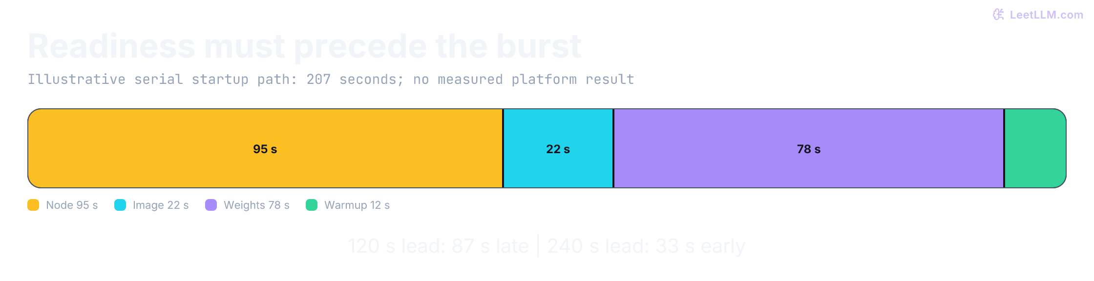
The cold start has four distinct phases, each with its own mitigation strategy. The ranges below are illustrative planning inputs, not platform guarantees; record your own p50 and p95 timings:
| Phase | Illustrative Duration | Mitigation Strategy |
|---|---|---|
| Node provisioning | 30-180s | Use warm pools, reserved capacity, or faster node images |
| Container pull | 10-90s | Use lazy pulling or container streaming so startup doesn't wait for the full image |
| Model weight loading | 30-180s | Keep weights on local NVMe or a warm shared cache close to the node |
| Runtime warmup | 5-30s | Prepare runtime artifacts and run readiness warmups; current TensorRT-LLM uses PyTorch without a separate engine-build step[9] |
Container streaming lets the container start executing before the entire image is downloaded. Required image data is fetched on demand, which can shorten startup but can also move fetching onto the first-request path; measure both.
Model caching can keep approved weights on local NVMe instead of fetching them from remote object storage on each start. A shared filesystem such as Amazon FSx for Lustre can supply multiple nodes. Measure cold reads and concurrent fleet loads: a shared cache still has throughput, network, and availability limits.
Some platforms also offer snapshot or restore features for a preloaded container or VM. Those can help, but they're more vendor-specific than warm pools plus local weight caches.
To mitigate cold start latency impact on users, engineers implement several proactive strategies:
- Over-provisioning: Keep a small headroom buffer to absorb sudden traffic spikes while new instances spin up.
- Predictive scaling: Use historical traffic patterns to scale up the cluster before anticipated usage spikes (e.g., scaling up just before the morning rush hour).
- Minimum warm pool: For high-priority workloads, retain enough measured warm capacity to protect the initial-burst TTFT target while cold replicas load.
This synthetic trace assigns 95 + 22 + 78 + 12 = 207 seconds to a serial startup path. It contains no platform measurements. Four minutes of lead time covers this one trace; production planning needs observed distributions and supply failures, not a sum of independent phase p95 values:
phase_seconds = {
    "node provisioning": 95,
    "container pull": 22,
    "weight loading": 78,
    "runtime warmup": 12,
}
illustrative_ready_s = sum(phase_seconds.values())

for lead_time_s in [120, 240]:
    spare_s = lead_time_s - illustrative_ready_s
    status = "ready before surge" if spare_s >= 0 else "surge sees cold queue"
print(f"lead={lead_time_s:3}s ready={illustrative_ready_s:3}s margin={spare_s:4}s: {status}")lead=120s ready=207s margin= -87s: surge sees cold queue
lead=240s ready=207s margin= 33s: ready before surgeWhich cold-start phase should you optimize if pods are scheduled quickly but first token still takes minutes?
Answer
Look at container pull, model weight fetch, and runtime warmup. Fast scheduling only proves a node exists; the model still needs image layers, weights, and readiness warmups before serving traffic.
Cost optimization
Measured capacity makes cost a decision boundary, not a guess. Running top-end GPUs 24/7 is expensive, and idle replicas burn budget fast. Keep the latency contract intact while choosing warm capacity, interruption risk, and platform ownership:
Spot instances and fault tolerance
Cloud providers offer spot instances at discounts, but they come with preemption risk. Inference can be easier to retry than long-running training, but reasoning runs and long generations may exceed a provider's warning window. Use measured request durations, a drain deadline, and retry behavior before assigning traffic to spot capacity.
For a code assistant, predictable launch-day or migration-week spikes can be candidates for spot overflow capacity when a stable baseline pool meets the promised SLO and interrupted work can drain or retry cleanly.
- Graceful shutdown: On
SIGTERM, remove the replica from new admission, let completions that fit the remaining drain budget finish, and retry or fail over requests that can't finish before termination. - Mixed pools: A common policy retains on-demand or reserved capacity for baseline SLO traffic and uses an autoscaling spot pool only for retryable overflow.
Why are spot GPUs often acceptable for inference but risky without drain logic?
Answer
Some inference requests finish within a preemption window or can be retried. Without drain logic, the load balancer keeps sending new work to a terminating node and active long generations are cut off without an explicit recovery path.
A provider warning is not a guaranteed extension of a Kubernetes termination grace period. Use the earliest actual shutdown deadline, reserve cleanup time, stop local admission immediately, and propagate cancellation. Remaining generation time is generally an estimate, not known in advance.
A streamed response can't usually be retried invisibly after bytes reach the client. The client needs an explicit interruption or supported resumption protocol; never append a new sample to an old partial answer. This synthetic decision check uses supplied remaining-time estimates and a 100-second finish budget:
import sys

def drain_action(remaining_s, *, streamed, deadline_s=100):
    if (type(streamed) is not bool
            or any(type(t) not in (int, float) or not 0 <= t <= sys.float_info.max
                   for t in (remaining_s, deadline_s))):
        raise ValueError("finite nonnegative durations and a boolean stream state required")
    if remaining_s <= deadline_s:
        return "finish if estimate holds"
    return "interrupt stream explicitly" if streamed else "retry within original request budget"

cases = [("short summary", 12, False), ("rollback summary", 84, True),
         ("long unstarted reply", 170, False), ("long active stream", 170, True)]
for name, remaining, streamed in cases:
    print(f"{name}: {drain_action(remaining, streamed=streamed)}")
assert drain_action(100, streamed=True) == "finish if estimate holds"
assert drain_action(101, streamed=True) == "interrupt stream explicitly"
for remaining in (float("nan"), float("inf"), True, 10**400):
    try:
        drain_action(remaining, streamed=False)
    except ValueError:
        pass
    else:
raise AssertionError("invalid work estimate accepted")short summary: finish if estimate holds
rollback summary: finish if estimate holds
long unstarted reply: retry within original request budget
long active stream: interrupt stream explicitlyScale-down cooldown & thrashing
A common (and expensive) mistake is scaling down too aggressively. If you terminate a GPU node because traffic dipped for 30 seconds, you'll pay the cold start penalty again when traffic returns a minute later. This "thrashing" can increase costs while degrading user experience.
Scale-down rules:
- Cooldown period: Start with a cooldown longer than short observed lulls and tune it against measured cold-start cost, idle spend, and recurring traffic patterns.
- Drain before terminate: Give the autoscaler time to drain in-flight requests before removing a replica. Don't kill a GPU mid-generation.
- Scale down gradually: Remove one replica at a time and wait to see if queue depth remains low before removing more.
Why can aggressive scale-down increase both cost and latency?
Answer
It repeatedly destroys warm capacity, then pays node provisioning and model loading again when traffic rebounds. The service burns startup time and money without serving useful requests during the cold-start gap.
Deployment options
When deciding how to deploy GPU inference, teams face a build-vs-buy decision:
| Operating model | What the platform owns | What you still verify |
|---|---|---|
| Managed/serverless inference | Much of scheduling, instance lifecycle, and scaling | Cold-start policy, minimum warm capacity, model support, limits, isolation, and billing |
| GPU instances or specialized GPU cloud | Hardware provisioning and selected infrastructure primitives | Engine lifecycle, queueing, health, capacity, storage, and failure recovery |
| Managed Kubernetes with GPU nodes | Kubernetes control-plane operation | GPU node pools, drivers/device plugins, engine replicas, metrics, scaling, and on-call ownership |
Compare total operating cost at the required SLO, not an isolated GPU-hour quote. Managed services can reduce platform work; self-managed serving gives more control but makes your team responsible for the control loops and failure modes in this lesson.
Diagnose a stalled spike
The incident assistant's queue is growing. Three synthetic traces suggest different interventions. Pick the next measurement before changing the fleet.
Trace A: a new replica becomes ready, then disappears during the next brief lull. Repeated startup timestamps establish flapping more directly than a noisy GPU-count graph. Compare lull lengths with readiness time and useful work served before termination. Tune downscale stabilization from that evidence and drain gradually. Count running work and active allocation pressure; evictable prefix-cache contents alone needn't block scale-down.
Trace B: successful requests average 800 ms, but some users wait 30 seconds. The mean hasn't established the promised tail experience. Inspect queue age, TTFT by prompt length, request TPOT, and stream-gap tails. Count rejects and timeouts as failed SLO attainment rather than excluding them from the denominator. If long prefills interrupt existing streams, compare chunked-prefill token budgets. Smaller chunks can shorten each interruption while increasing their frequency; chunking doesn't make prompt work free.[13][4]
Trace C: callers time out and immediately retry while all workers remain full. Adding desired replicas won't clear this queue before they become ready. The immediate control point is admission: bound waiting work, carry the original deadline, and reject requests that can't start within their budget. Track queue age as well as depth, and constrain retries so rejection doesn't become another traffic source.
The failure path is an explicit reject, not a timeout after the KV pool is already full:
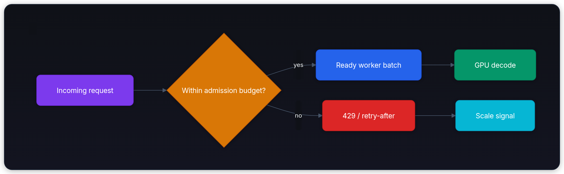
A bounded queue and an explicit overload response preserve more useful work than unlimited retries. A 429 isn't a guarantee that the next retry will fit; the caller still needs a deadline and retry budget.
Sometimes the aggregate curve hides which requests compete:
| New evidence | Next comparison |
|---|---|
| Interactive TTFT degrades only when batch analytics runs | Split results by traffic class and tenant; test fair scheduling, limits, or separate pools |
| Short-prompt tests pass, but longer histories exhaust admission capacity | Recompute growing KV plus hybrid state using real prompt/output distributions and active concurrency |
| PagedAttention reduces reserved memory, but repeated prompts still require prefill | Inspect prefix reuse separately from block allocation; paging alone doesn't skip computation |
Finally, compare old and new replicas. Going from two to ten workers can initially increase TTFT if routing shifts requests from hot prefix caches to cold ones. Verify cache-hit and queue differences before calling the scale-up a regression. Approved synthetic warmup can populate eligible shared prefixes, but it must use the same model, adapter, template, and cache-isolation identity as the eventual traffic. A different tenant salt or changed prefix won't warm the intended entry.[8]
Why might new replicas make TTFT worse right after a scale-up?
Answer
Old replicas may have hot prefix caches, while new replicas start cold. If traffic shifts immediately, the new replicas recompute shared prompt prefixes and first-token latency rises despite higher replica count.
When the baseline isn't enough
The baseline handles many fleets. The options below change the data plane or the failure boundary, so measure the simpler path first and add one only when the trace names a bottleneck.
Prefill-decode disaggregation
Prefill and decode stress GPUs differently. Prefill processes many prompt tokens in parallel and tends to be compute-heavy. Decode produces one token per active request and tends to be memory-bandwidth-heavy. If you run both phases on the same worker pool, a few long prompts can delay short streaming responses, and decode traffic can leave tensor cores underused.
Prefill-decode disaggregation, studied for production serving by Splitwise and DistServe, splits the serving fleet into two pools:[22][14]
- Prefill workers ingest prompts, build the initial KV cache, and hand off cache state.
- Decode workers continue token generation for active requests with tighter scheduling around TPOT.
This isn't free. You now need cache transfer, placement logic, and backpressure between pools. But it can help high-traffic systems where long prompts and streaming generations compete for the same GPU budget. The autoscaling signals also become more specific: prefill workers scale on prompt-token backlog and TTFT, while decode workers scale on active sequences, KV-cache utilization, and TPOT.
Follow one request across the data plane
Disaggregation changes which worker owns each phase. The frontend or router first chooses a compatible prefill worker, using load and, when useful, prefix or cache locality. That worker processes the prompt and builds the initial KV blocks. A transfer layer then moves those blocks and the metadata needed to interpret them to a decode worker. Both sides must agree on model, dtype, block size, and KV layout, or the handoff can't be trusted.[4]
The decode worker admits the sequence, runs token steps, and streams the answer. Cancellation and timeout must release state on both sides, while backpressure must reach the router before either pool accumulates work it can't finish. Placement matters too: a split that sends large KV transfers across a slow link can give back the goodput it was meant to recover.
NVIDIA Dynamo is one documented open-source control-plane example. Its documentation describes disaggregated prefill and decode deployments across backends including vLLM, SGLang, and TensorRT-LLM, with KV-aware routing and KV-transfer mechanisms for split deployments.[4] This makes it a useful implementation to study, but the operational win still depends on measured prompt mix, transfer cost, and cache-hit behavior.
Don't start here. First tune continuous batching, chunked prefill, prefix caching, and queue policy. Disaggregation is a later optimization when one mixed pool can no longer hit both TTFT and TPOT targets, with any missed objective reducing dual-SLO goodput.
When does prefill-decode disaggregation become worth the extra system complexity?
Answer
Use it when long prompts and streaming decode traffic fight inside one worker pool after simpler fixes are exhausted. It helps when separate prefill and decode autoscaling signals are needed to restore goodput (request rate under both TTFT and decode SLOs).
Use measurements, not architecture fashion, to decide whether to split pools. This gate recommends investigation when a tuned mixed pool misses either declared service objective under a synthetic trace. Both objectives must be met; both needn't fail before investigating contention:
workload_trials = [
    {"name": "decode-only pressure", "long_prompt_share": 0.20, "ttft_p95_ms": 800, "tpot_p95_ms": 90},
    {"name": "short incident chat", "long_prompt_share": 0.08, "ttft_p95_ms": 820, "tpot_p95_ms": 44},
    {"name": "policy-document surge", "long_prompt_share": 0.61, "ttft_p95_ms": 2450, "tpot_p95_ms": 93},
]
ttft_slo_ms = 1500
tpot_slo_ms = 60

for trial in workload_trials:
    slo_miss = trial["ttft_p95_ms"] > ttft_slo_ms or trial["tpot_p95_ms"] > tpot_slo_ms
    action = "trace contention; compare split pools" if slo_miss else "mixed pool meets these gates"
print(f"{trial['name']:23} long-prompts={trial['long_prompt_share']:.0%} -> {action}")decode-only pressure long-prompts=20% -> trace contention; compare split pools
short incident chat long-prompts=8% -> mixed pool meets these gates
policy-document surge long-prompts=61% -> trace contention; compare split poolsSpeculative decoding
Speculative decoding speeds up generation by using a smaller "draft" model to predict multiple tokens ahead, then verifying them with the larger "target" model. Leviathan et al. report roughly 2-3x acceleration in their evaluated settings, not a universal serving guarantee.[23]
The speedup comes from amortizing target-model work across several draft tokens. The draft model's predictions are treated as hypotheses; the target model evaluates them in one verification pass and keeps the accepted prefix. Acceptance preserves the target generation rule; it doesn't certify factual correctness. It still pays draft-model compute and rejection overhead, so you measure it against your own workload instead of assuming it always helps.
For a Qwen3.6-27B target, first verify that the selected speculation method, backend, draft or prediction module, and token mapping are compatible; an arbitrary small model isn't a supported pairing. The draft proposes candidates and the target evaluates candidate positions together. Greedy verification accepts matching target tokens up to a mismatch; distribution-preserving sampling instead needs probability-ratio acceptance and corrected sampling on rejection. A simple equality check is not the general sampled algorithm.[23]
When is speculative decoding most likely to help a serving fleet?
Answer
It helps decode-heavy, memory-bandwidth-bound workloads when a cheap draft model predicts a high fraction of target-model tokens correctly. It's less useful when prefill, retrieval, queueing, or network latency dominates.
Multi-region failover
GPU quota and available capacity vary by region and time. If the primary region is at capacity or unhealthy, the incident assistant still needs a path to a secondary region.
This requires:
- Eligible routing: Choose a healthy region that can meet the remaining request budget and is allowed to serve that tenant's data and tools.
- Release parity: Resolve the same approved model, tokenizer, adapter, prompt/template, retrieval data, and safety/tool policy. Verify readiness for that release before sending traffic.
- Recovery logic: Test the secondary region's actual ready capacity. Preserve tenant authorization, cancellation, and original deadlines when shifting new or retryable requests.
Regional failover is particularly important for spot instance workloads. If a regional spot fleet is reclaimed, your tested recovery-time objective determines whether secondary on-demand capacity can receive new requests before client timeout budgets expire. Long in-flight generations still need retry or resumption semantics.
What must be synchronized before multi-region failover is safe for tenant-specific models?
Answer
Resolve the approved base model, LoRA adapter, tokenizer/config, prompt/template, retrieval data, and safety/tool policy in an eligible healthy region. Recheck tenant authorization and ready capacity. Matching weights alone can't preserve the application behavior or grant permission to move a request.
Multi-tenancy with LoRA
Instead of deploying a separate Qwen3.6-27B base for every customer fine-tune, use one shared base model and select LoRA (Low-Rank Adaptation)[24] adapters per request. Systems like S-LoRA[25] show how to batch requests across different adapters while keeping the base model weights shared in GPU memory. vLLM also supports per-request LoRA serving, with explicit warnings around separate runtime adapter-loading APIs in untrusted environments.[26]
Select adapters from authenticated identity supplied by trusted middleware, never directly from an X-Tenant-ID header. The CPU policy below deliberately denies missing, unknown, cross-tenant, and revoked identities. The principal is a trusted in-process value, not a signed token verifier; a production authentication layer must validate credentials before constructing it.
from dataclasses import dataclass

@dataclass(frozen=True)
class Principal:
    subject: str
    tenant: str

@dataclass(frozen=True)
class Adapter:
    name: str
    numeric_id: int
    path: str
    base_revision: str

registry = {
    "tenant_A": Adapter("adapter_A_v3", 101, "/approved/tenant_A/revision-3", "base-v7"),
    "tenant_B": Adapter("adapter_B_v2", 102, "/approved/tenant_B/revision-2", "base-v7"),
}
memberships = {("alice", "tenant_A"), ("bob", "tenant_B")}

def select_adapter(principal, requested_tenant, loaded_base="base-v7"):
    if principal is None or principal.tenant != requested_tenant:
        raise PermissionError("tenant identity mismatch")
    if (principal.subject, principal.tenant) not in memberships:
        raise PermissionError("membership missing or revoked")
    adapter = registry.get(principal.tenant)
    if adapter is None or adapter.base_revision != loaded_base:
        raise PermissionError("approved compatible adapter unavailable")
    return adapter

alice = Principal("alice", "tenant_A")
assert select_adapter(alice, "tenant_A").numeric_id == 101
for principal, tenant, base in [(None, "tenant_A", "base-v7"),
                                (alice, "tenant_B", "base-v7"),
                                (Principal("mallory", "tenant_A"), "tenant_A", "base-v7"),
                                (alice, "tenant_A", "base-v8")]:
    try:
        select_adapter(principal, tenant, base)
    except PermissionError:
        pass
    else:
        raise AssertionError("unauthorized adapter selected")
memberships.remove(("alice", "tenant_A"))
try:
    select_adapter(alice, "tenant_A")
except PermissionError:
    print("PASS approved route; missing, cross-tenant, unknown, wrong-base, revoked deny")
else:
raise AssertionError("revoked membership accepted")PASS approved route; missing, cross-tenant, unknown, wrong-base, revoked denyAfter policy selection, the trusted engine integration constructs LoRARequest(adapter.name, adapter.numeric_id, adapter.path) and passes it to a LoRA-enabled engine. That API path is documented, but no GPU engine or adapter is loaded by this exercise.[26] Deny unavailable adapters instead of silently falling back to the base model. Registry paths must resolve to verified immutable artifacts; this example's paths are placeholders.
LoRA selection isn't a complete tenant boundary. Enforce tenant permissions on prompts, retrieved context, tools, logs, and result caches too. For sensitive prefix reuse, assign cache_salt from the trusted tenant or sharing-group policy; accepting arbitrary salts from callers doesn't establish authorization.[8]
What is the main safety risk in LoRA multi-tenancy?
Answer
Runtime adapter loading can become a code and data isolation boundary. Only load approved adapter paths, bind tenant IDs to authorized adapters, version adapters immutably, and avoid accepting arbitrary adapter locations from requests.
Choose the next capacity change
The release-freeze spike now has a decision path. Trace a request from arrival through queueing, prefill, cache allocation, decode, and streaming. Then measure the same path under a realistic arrival process, with declared TTFT and decode SLOs.
If the queue grows before the first token, inspect admission, cold readiness, prefill, and cache pressure. If token gaps grow after streaming starts, inspect decode bandwidth, active sequences, and batching. A Kubernetes pattern using KEDA/HPA, a GPU node autoscaler, and a serving engine can act on those signals, but only after measured capacity gives it a meaningful threshold.
Continuous batching and PagedAttention improve GPU use, yet they don't remove cold starts or capacity variance between nodes. Choose warm capacity, quantization, a batch limit, or a split prefill/decode data plane only when the evidence shows which constraint moved. Keep admission limits and queue deadlines in place while that change takes effect.